Through the evolution of 3D-printers, the it has become more and more easy to produce prototypes of 3 dimensional shapes. In this project we developed our first software to produce shapes and printable objects for a 3D-printer. This project was part as a final project of the École Polytechnique course “X-INF 574 Digital Representations and Analysis of Shapes”.
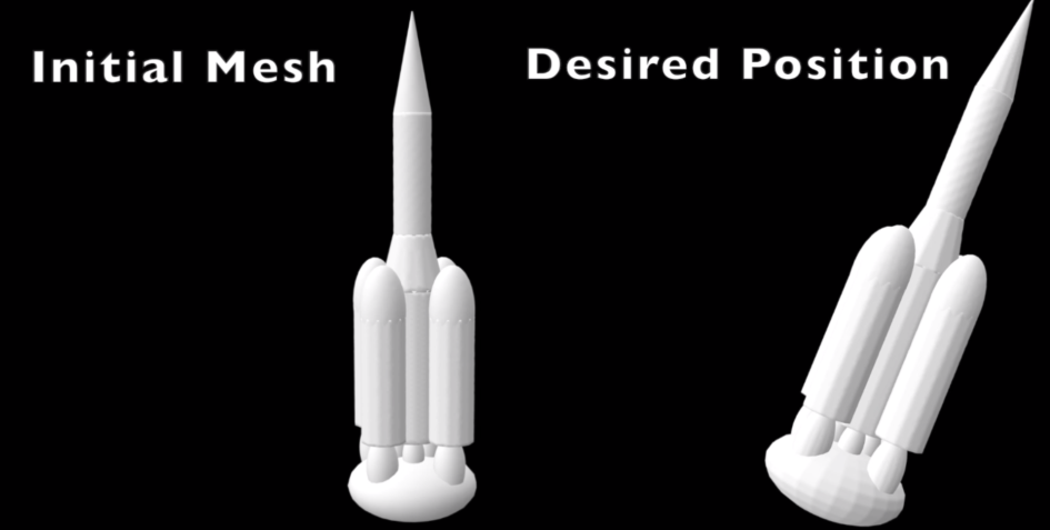
The aim of this project was to give an input shape, define an angle an orientation axis and then to carve out and deform the shape, such that the new modified shape can stand in this desired position.
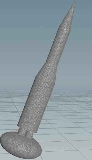
 |
|---|
| We want to have a rocket in a tilted position, that can stand stablely. |
The scientific foundation for this project can be found in Prevost et al. We were both not part of the work, we just tried to reproduce their idea and to gain experience with 3d-printing soft- and hardware.
 |
|---|
| Further examples of shapes in tilted positions. |
In this post we will first describe the rough roadmap and afterwards we will get into detail how we implemented all this precisely.
Roadmap
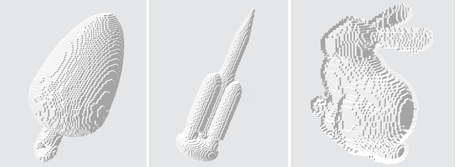
In the first part of the project we focused to get a discrete voxelized representation of our three dimensional shapes.
 |
|---|
| Voxelization of three dimensional shapes. |
Note that we assume, that the tilting already took place before the creation of the .obj file.
This can be done for example with Houdini SideFx Software, later we will discuss how this can be done precisely.
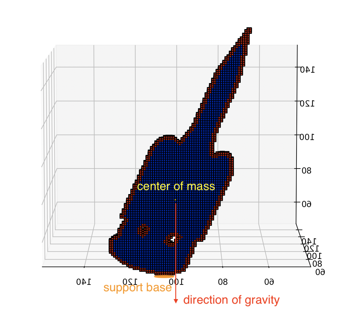
Once we have this boolean volumetric representation of the (tilted) shape, we determine a support base on which the object should be able to stand on without falling.
 |
|---|
| Support base of the rocket with indicated boundary voxels. |
Further we determine which voxels belong to the boundary and which are part of the inner of the shape as seen in the upper image. Next we determine the center of mass and check, in which way the center of mass is away from the from the support base. Once this is determined, we start to carve the inner vertices until either the center of mass is inside the support base and the shape can stand stablely.
 |
|---|
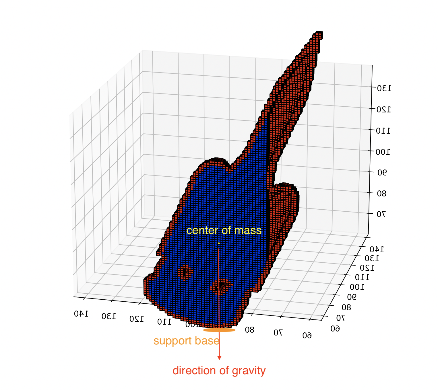
| Center of mass inside the support base :). |
In this case we are done and we can start to print the shape. It might happen, that we carve layer by layer through the shape and pass the support base, but the center of mass does not end up in the support base. In this case carving alone is not sufficient. If the object is for example very tall and thin, it also makes intuitively sense, that if the shape is tilted heavily in one direction, carving alone might not be sufficient.
In order to overcome this issue, we came up with two options. The first one is -if it is possible- to add further mass to stabelize the figure, such that the center of mass becomes moved by that amd the carving can be more efficient.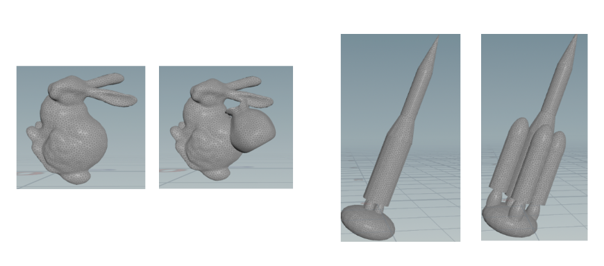
The second option is to deform the shape, such that the features of the shape are preserved, but at the same time the mass distribution becomes improved.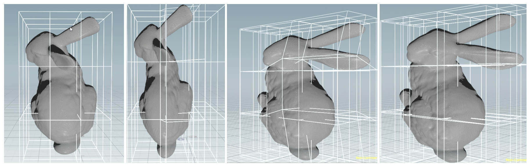
In the initial paper mentioned above they suggested an alternating algorithm between deforming and carving in order to improve the weight distribution of the shape.
Implementation
Well, so far these rough ideas might not seem that difficult, but then you get to the point, where you just want to take the mesh and get a stable .stl file, it is a bit challenging.
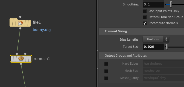
We made use of Houdini Software for the purposes, because a lot of the file type conversion, mesh smoothing or cage deformations can be done there quite easily.
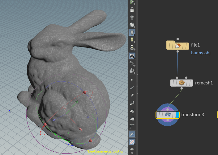
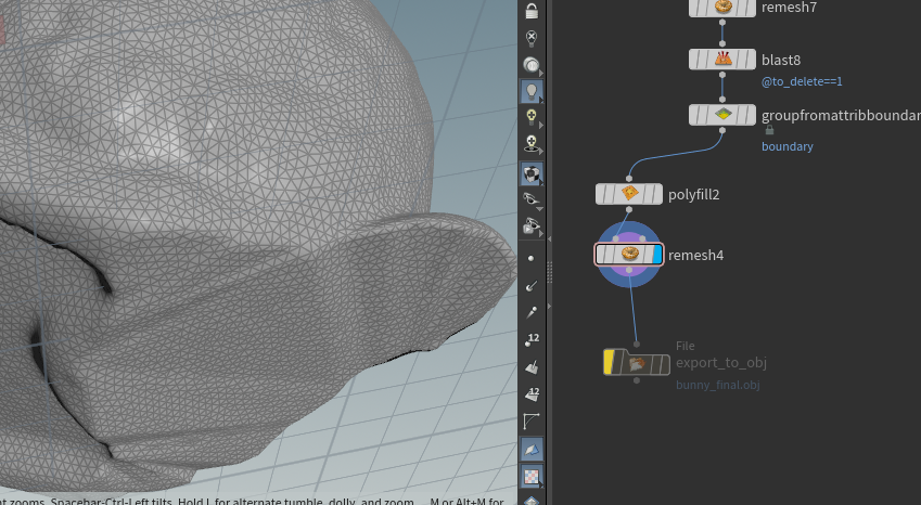
In order to create an .obj file of a shape, that is tilted, we first start to import an .obj of the shape with a file node in Houdini and remesh it.
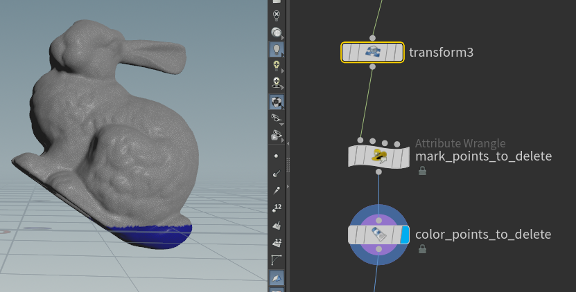
In the code of the pointwrangle mark_to_delete add the code
if(v@P.y<0){
    i@to_delete=1;
}
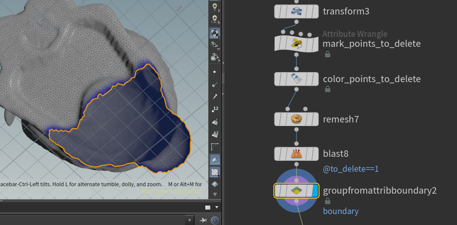
Now use a blast node to delete the blue vertices
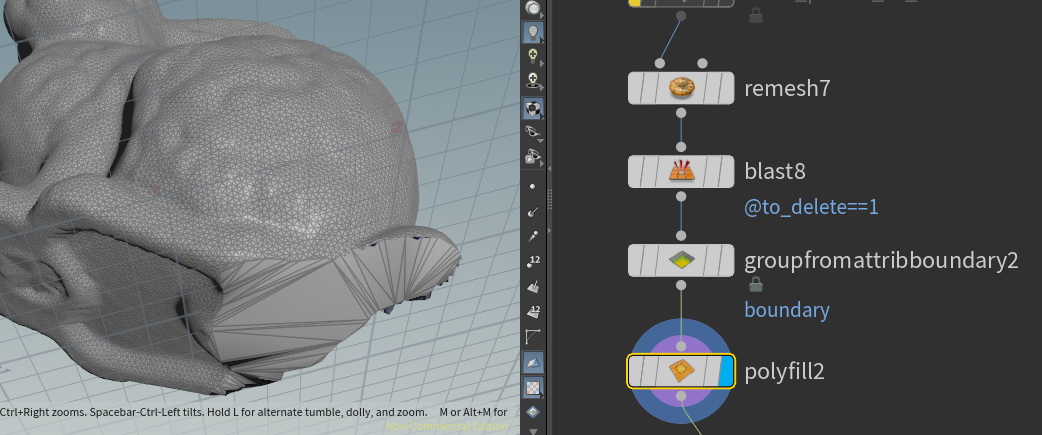
To fill this hole, we use a polyfill node. But before we can do that, we need to declare which hole it should fill. To do this, we need to declare a boundary first.
Once we have the tilted inital mesh, we can start with the voxelization process.
Voxelization
For that we made use of the Open3d and followed their tutorial to convert a triangulated mesh into a voxelized surface, more precisely the code we used can be found here. Their code cell [5] was of great use for our purpose, because it turns the mesh into a dense voxelized grid together with a voxelized surface. Our code then becomes first:
import open3d as o3d
import numpy as np
import pdb
import json
import os
import pdb
import copy
#from scipy.sparse import csr_matrix

from carve_voxel import voxel_carving
[...]
name= "bunny_final"
#name = "bunny_flipped_3"
#name= "rocket_turning_flipped_2"


mesh_path = "./data/"+name+".obj"
mesh = o3d.io.read_triangle_mesh(mesh_path)
output_voxel_filename = os.path.abspath("./data/"+name+"_voxelized.obj")
output_mesh_filename =os.path.abspath("./data/"+name+"_scaled.obj")
camera_path = os.path.abspath("./data/sphere.ply")
np_file = "./data/"+name+"_voxel"
json_filename = "./data/"+name+"_voxel.json"

visualization = True
cubic_size = 2.56 # 128 * 0.04
voxel_resolution = 256.0 #
mesh_scale = 10.0
print("surface mesh")
print(mesh)
o3d.visualization.draw_geometries([mesh])
mesh, voxel_grid, voxel_carving, voxel_surface = voxel_carving(mesh, output_voxel_filename, camera_path, cubic_size, voxel_resolution)
# We can directly zoom out mesh a little bit
# to make sure that the voxel is inside
mesh.scale(mesh_scale, center=mesh.get_center())

o3d.io.write_voxel_grid(output_voxel_filename,voxel_grid)
o3d.io.write_triangle_mesh(output_mesh_filename, mesh)
In this example in the line from carve_voxel import voxel_carving, the module carve_voxel is mainly the mentioned code block [5] from the Open3D tutorial. Note that the parameter voxel_resolution will be cubed! Therefore one needs to be careful with this parameter. In our tests a parameter of 256 was at the upper maximum of what we could compute in a reasonable time.
N_index = int(voxel_resolution)
voxel_matrix = np.zeros((N_index,N_index,N_index))
voxel_matrix = voxel_to_numpy(voxel_grid, voxel_resolution = N_index)
Here we create a numpy array with the size “N_index x N_index x N_index”, where we will save the boolean information whether a grid cell is included in the voxelized shape.
In this case the function voxel_to_numpy(...) is given by
def voxel_to_numpy(voxels, voxel_resolution = 64):
    """
    Input: An instance if the open3d voxelgrid datastructure, the number of voxels per sidelength (voxel_resolution)
    Output: A numpy array of voxel_resolution x voxel_resolution x voxel_resolution with 1 and 0, where ever we have a voxel or not
    """
    vx_numpy = np.zeros((voxel_resolution,voxel_resolution,voxel_resolution))
    grid = voxels.get_voxels()
    for i in grid: # index is from 1 to scale/size
        #print(i.grid_index)
        voxel_index = i.grid_index #a[0] a[1] a[2]
        vx_numpy[voxel_index[0]-1,voxel_index[1]-1,voxel_index[2]-1] = 1
    return vx_numpy
I am not very proud about this implementation, it seems a bit dump and it is not very quick, but it is efficient.
Lastly, to finalize the file voxelizer.py, we need to add the lines,
inside, surface = voxel_carv_preprocess_numpy(voxel_matrix, thickness=1)
np.save(file="./data/"+name+"_voxel_surface",arr=np.array(surface, dtype=bool))
np.save(file="./data/"+name+"_voxel_int",arr=np.array(inside, dtype=bool))
where we basically seperate the inner voxels from the surface and can prescribe the thickness of the boundary. We save them as numpy arrays, because with the special naming of the files the carving.py file will be able to read them out directly.
Carving
If we named the files correctly, the first lines of our carving program will be to load the numpy arrays, that have been created in the voxelization program, i.e
#name= 'rocket_flipped'
#name='rocket_turning_flipped_2'
#name = "bunny_flipped_3"
name = "bunny_final"

voxel_surface = np.load('data/'+name+'_voxel_surface.npy')
voxel_inside = np.load('data/'+name+'_voxel_int.npy')


voxels = voxel_inside + voxel_surface
The first part of the carving will be to determine, where we will have our support base for the carving, i.e a rectangle of voxels, where the center of mass should end up. We start to search from the bottom to the top to the first layer in y-direction, where we have a voxel. Then we go one layer above, because it turned out that difficulties in the termination of the algorithm can occur, when we take directly the first layer. Next we look for the largest rectangle contained in this layer. This will be our support base. As a code, this function has the following form
def support_base(voxels_np):
    """
    Input: A numpy array (full) with the information whether the voxel is contained
    Output: the range of support bsae
    NOTE: The y axis is perpendicular to the support base.
          The support base is close to y=0
    """
    grid_shape = voxels_np.shape
    for id_y in range(grid_shape[1]):
        if(np.count_nonzero(voxels_np[:,id_y,:]==True)>0):
            #id_y+=1 #NOTE: After visualization, second floor is connected
            support_base = voxels_np[:,id_y,:]
            support_index = np.nonzero(support_base)
            #pdb.set_trace()
            max_x = np.max(support_index[0])
            min_x = np.min(support_index[0])
            max_z = np.max(support_index[1])
            min_z = np.min(support_index[1])
            center = np.array([int((max_x+min_x)/2), int((min_z+max_z)/2)])
            scaled_support_base = np.full((grid_shape[0],grid_shape[2]),False)
            #Here we manually set the size for the support base
            #This is chosen purely from intuition and it is possible that there are better choices.
            scaled_support_base[center[0]-1:center[0]+1,center[1]:center[1]+1] = True
            if((np.logical_and(scaled_support_base,support_base)==scaled_support_base).all()):
                print("Support base is reasonable!!")
                return scaled_support_base
Then the support base can be of the form
To compute the center of mass, we just compute the mean of all x-,y- and z-components, i.e
def center_of_mass(voxels_np):
    """
    Input: A numpy array (full) with the information whether the voxel is contained
    Output: The grid coordinates of the center of mass
    """
    grid_shape = voxels_np.shape
    counter = 0
    center = np.array([0.,0.,0.])
    for id_x in range(grid_shape[0]):
        for id_y in range(grid_shape[1]):
            for id_z in range(grid_shape[2]):
                #check whether we hit a a voxel in the mesh
                if(voxels_np[id_x,id_y,id_z]==1):
                    counter+=1
                    center = (1/float(counter))*np.array([float(id_x),float(id_y),float(id_z)]) + (float(counter-1)/float(counter))*center

    return([int(center[0]),int(center[1]),int(center[2])])
If these are calculated, we can start with the carving process.
def carving(voxel_surface,voxel_inside,support_base):

    grid_shape = voxel_surface.shape
    carved_voxel_inside = voxel_inside
    support_index = np.nonzero(support_base)
    max_x = np.max(support_index[0])
    min_x = np.min(support_index[0])
    max_z = np.max(support_index[1])
    min_z = np.min(support_index[1])
    com = center_of_mass(voxel_surface+voxel_inside)
    com_x = com[0]
    com_z = com[2]

    if(com_x>=min_x and com_x<=max_x and com_z>=min_z and com_z<=max_z):
        return carved_voxel_inside
    # to move com_x, cut y-z plane
    # to move com_z, cut y-x plane

    if(com_x<min_x):
        [...]
We check if the center of mass is already in the desired area, if not, we check where we need to take away mass in order to move the center of mass inside the support base.
def carving(voxel_surface,voxel_inside,support_base):
    [...]
    if(com_x<min_x): #cut y-z plane
        #pdb.set_trace()
        for i in range(grid_shape[0]):

            if(carved_voxel_inside[i,:,:].any()==False):
                print("for x, skip ",i)
                continue
            else:
                cut_x = i
                print('entered')
                break

        while(com_x<min_x and cut_x<grid_shape[0]):
            print("com_x=",com_x)
            print("min_x=",min_x)
            print("cut_x=",cut_x)
            print("com_z=",com_z)
            print("================")
            if((min_x-com_x>0) ):
                carved_voxel_inside[cut_x:cut_x+5,:,:]=False
                cut_x+=5
            else:
                carved_voxel_inside[cut_x,:,:]=False
                cut_x+=1
            com = center_of_mass(voxel_surface+carved_voxel_inside)
            com_x = com[0]
            com_z = com[2]

    [...]
We basically search for the first layer, that we can remove. If we are far enough away from the support base with the leading carving layer and the center of mass, we cut away several layers at once. After each carving step we recalculate the center of mass of the carved shape and verify if the center of mass is in the support base now.
def carving(voxel_surface,voxel_inside,support_base):
    [...]
    if(com_x<min_x):
        [...]
    if(com_x>max_x):
        [...]
    if(com_z<min_z): #cut y-x plane
        [...]

    if(com_z>max_z):
        [...]

    if (com_x >=min_x and com_x <=max_x and com_z >=min_z and com_z <=max_z):
        print("Carving is successful! The new center of mass is in the support base!")


    return carved_voxel_inside
If the algorithm does not terminate, carving is not sufficient! In this case one either needs to add mass and repeat the carving process.
The other option is to deform the shape. In the original paper, they deformed the carved shape. In our attempt, we had some struggle to retransform the carved boolean shape in an inner and outer mesh in an .obj format. Our solution is therefore a semi automatic approach. We print out the values of the current carving plane and the center of mass. If the carving fails, one can deduce where we need to add more mass and how we need to deform them. Prevost et al used an energy from the bounded biharmonic weights with deformation handles in order to achieve the deformation. In our approach we use a cage based deformation in Houdini to deform the shapes. It should be noted, that this needs to be done before the carving process, we were not able yet to implement an alternating carving and deforming.
Deformation with Houdini
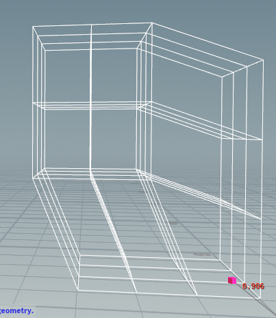
In order to implement a cage based deformation in Houdini, we need to define a bounding box first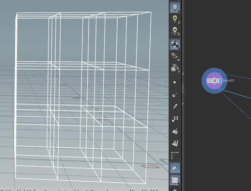
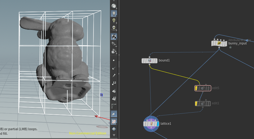
To use an edit node, one needs to select first a number of points inside the cage.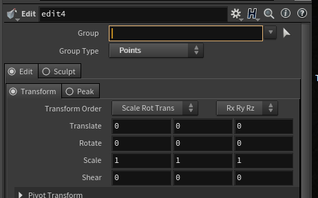

Once these nodes are selected, the selection of nodes can be moved around.
If the transformation is applied, and we merge them together properly, the result could look like that: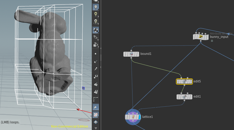
If you do this a few times, you will notice in which way it is benefitial to deform the shape, before starting the carving.
STL-Files and printing
If the carving was successful you still cannot print it, because for the 3D-printing, you need a file in a .stl format. That means basically, that you save the shape layer by layer. Fortunately there is a Python module called voxelfuse to do that. The code to export the numpy array into a .stl file is then given by
from voxelfuse.voxel_model import VoxelModel
from voxelfuse.mesh import Mesh
from voxelfuse.primitives import generateMaterials
import numpy as np

if __name__ == '__main__':

    voxel_numpy = np.load('data/bunny_final_voxel_entire_carved.npy')
    model = VoxelModel(voxel_numpy, generateMaterials(4))
    mesh = Mesh.fromVoxelModel(model)
    mesh.export('bunny_final_scaled_carved.stl')
Now, if everything went well, you should have a printable file now.
Thanks to the Télécom Paris Fablab we were able to print our shapes with their 3D-Printer. We used a Creality3D CR-10S Pro Imprimante 3D to start printing our models.
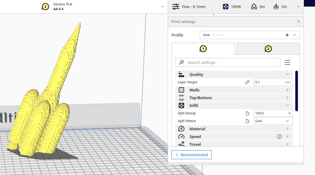
Before starting the printing process, we use the Ultimaker Cura Software to prepare our 3D prints.
Make sure, that you increase in the printer settings the infill to 100%, since we want to use the mass of the infill for the balancing.
The Ultimaker software then creates “a roadmap” for the 3D-printer at what time it should travel with the nozzle to which position with which speed, also to create the support.
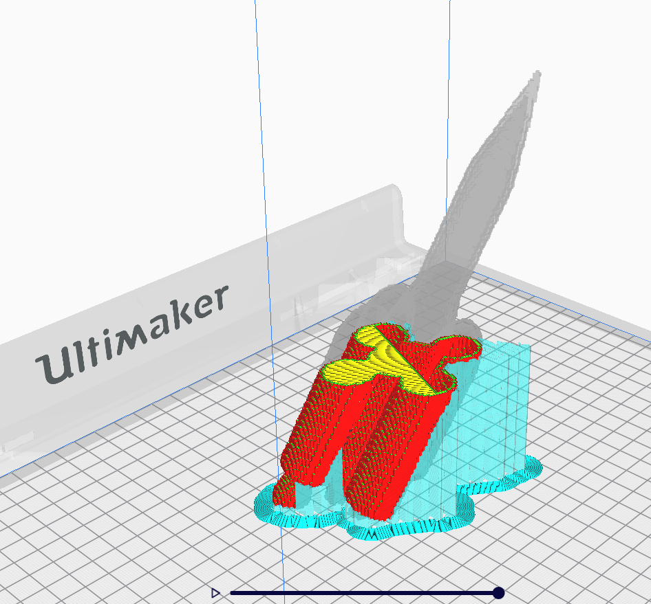
This plan can then be saved to disk and excecuted by the 3D-printer.
The successful models can be seen here for example
Nevertheless, one needs to be careful with the thickness and position of the boundary. If the boundary is too thin and has no support behind it, the surface easily breaks.
Nevertheless, you can still get your tilted christmas tree pinecone :)
The code for this project can be found under https://github.com/JeansLli/X-INF574_3D-printing